This page describes an investigation of line tracing with a vibrotactile array. Results suggest that the spatial information provided to the fingertip by the array offers a significant advantage. The hardware and original software were developed by Alan Brady and Ian Summers. The software was further developed by Tom Loughran and Rob Valkass, who also carried out the experiment. These results were presented at the 2013 Euromov Conference in Montpelier, France.
MOTIVATION
A vibrotactile array can deliver spatially distributed touch information to the fingertip during active exploration of a virtual environment. However, such multi-contactor devices are difficult to implement, raising the question of whether information from stimulator arrays is significantly more useful than that from single-contactor alternatives.
OVERVIEW
A line-tracing experiment has been performed, involving exploration of a 2D virtual environment via a 25-contactor array on the fingertip (5 × 5 array with 2 mm spacing, 40 Hz stimulation). This hardware (Fig. 1 and Fig. 2) was developed as part of the EU-funded ENACTIVE project. Participants were required to trace the index finger along virtual lines, composed of corners and straights, within a 30 cm x 21 cm workspace (Fig. 3). In the “array” condition, the position and shape of the line on the fingertip were represented as vibration of the appropriate contactors. In the “pad” condition, all contactors in the array were vibrated when the fingertip lay over the virtual line, i.e., no spatial information was provided on the fingertip. Subjects were also required to complete a corresponding “real-world” task involving raised-line maps.
METHOD
Following a short session of training and familiarisation, each participant (blindfolded) traced maps of varying radius: 7 in the pad condition, 7 in the array condition, and 7 in the real-world condition. Participants were asked to perform the task as rapidly as they felt comfortable, and were informed of a two minute cut-off time. The time taken to complete each map was recorded, along with the time spent on the line. This allowed an “accuracy” figure to be calculated as a ratio of the time spent on the line to the total time. Speed and accuracy values were normalised to each participant’s average speed and accuracy over the 7 real world raised-line maps
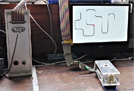
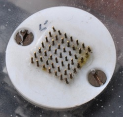
Figure 1: The array comprises 25 vibrating contactors driven by piezoelectric actuators, surrounded by 24 static contactors, with 2 mm spacing.
Figure 2: The array moves in a 2D workspace under the control of the participant. The virtual environment, including the line to be traced, is shown on the monitor (not visible to participants). The red square on the monitor indicates the area represented on the array.
RESULTS
In the array condition, participants’ speed was around 40% of their real-world speed; in the pad condition, participants’ speed was less than 20% of their real-world speed (Figure 4). The difference between the array and pad conditions was found to be statistically significant (p<0.001, Student t test). In the array condition, participants’ accuracy was over 90% of their real-world accuracy; in the pad condition, participants’ accuracy was around 65% of their real-world accuracy (Figure 5). This difference between the array and pad conditions was also found to be statistically significant (p<0.001, Student t test). The effect of corner radius on speed and accuracy was not significant, in either case.
CONCLUSIONS
In line tracing tasks the array condition was found to have a significant advantage over the pad conditions in both speed and accuracy of use. Anecdotal reports suggest that, in the array condition, spatial information on the fingertip allowed participants to plan ahead and so achieve a better movement strategy.
TECHNICAL DETAILS
The control electronics is the box to the left of Figure 2. Sinewave drive signals for the 25 channels of the stimulator are generated by a master oscillator, which has preset frequency and amplitude. Individual channels are either “on” or “off”, according to the settings of digitally controlled switches, providing a spatial pattern of stimulation to the user’s fingertip . The stimulator is moved around the workspace by the user’s exploratory movements – it is attached to a computer mouse which provides positional information to the control computer. This computer has a software model of the virtual tactile environment, and provides control signals to the stimulator channels to produce an appropriate pattern of touch sensation on the user’s fingertip.
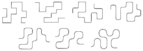
Figure 3: Examples of lines within the 2D workspace; corner radius varied from 0 mm to 30 mm in 5 mm steps.
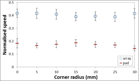
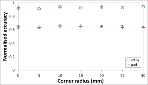
Figure 4: Speed in the pad condition was significantly lower than in the array condition; variation of corner radius in the lines to be traced had little or no effect.
Figure 5: Accuracy in the pad condition was significantly lower than in the array condition; variation of corner radius in the lines to be traced had little or no effect.
Virtual Touch 1 Click here for a related video on YouTube